A blow mold is not a shaped hole in a block of metal. It is a stack of components, each with its own material specification, its own dimensional tolerance and its own cooling duty — and that stack, not the cavity shape, is where the cost of a tool actually sits. In extrusion blow molding (EBM) the finished tool is really two assemblies: the blow mold that forms the container, and an automatic flash trim unit that shears the tail at the base and the flash at the neck while the mold is still clamped. The numbers below come from production drawing sets for HDPE and PP containers, cross-checked against published mold-making capability tables, so a buyer can read a tooling quotation and know what is being promised.
What a blow mold actually consists of
A tool supplied without a trim unit does not remove that work — it moves it to an operator, on every cycle, for the life of the mold. Everything else in the assembly exists to do three things: hold the parison at the right place, freeze it fast, and release the finished bottle without flash.
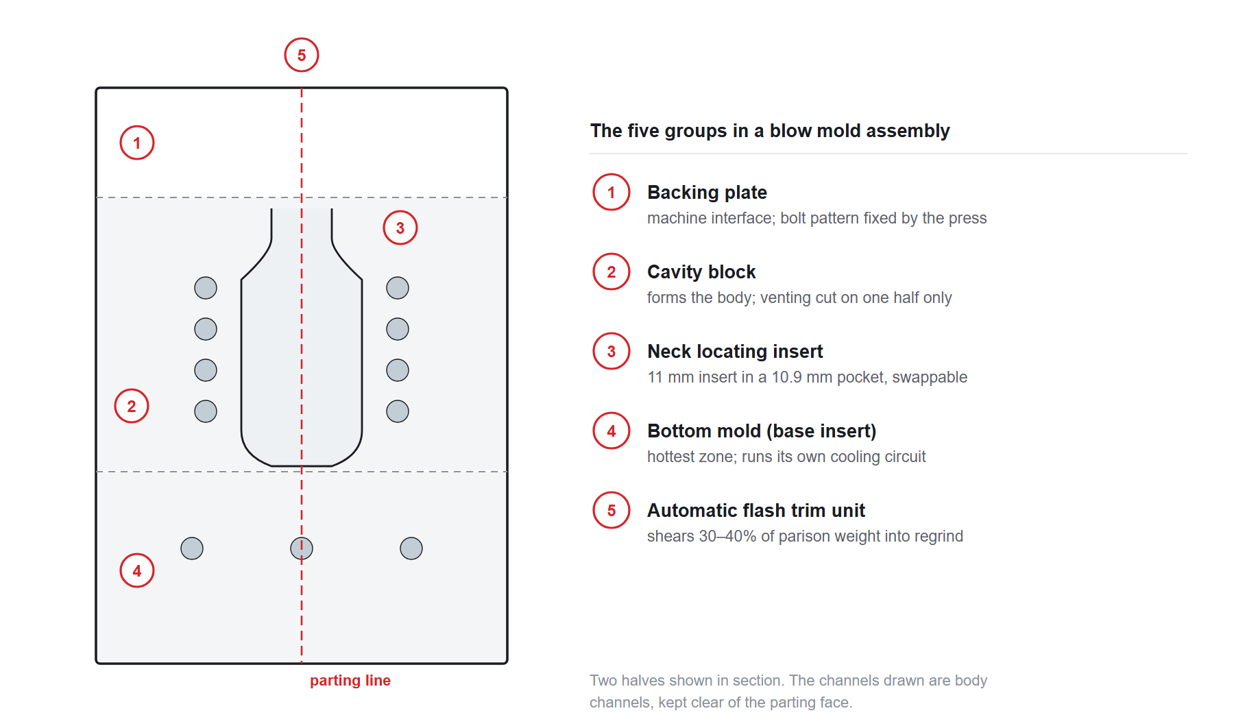
1. Cavity block
The cavity block forms the bottle body and carries most of the tooling’s precision. A typical drawing set specifies a locating pin of Ø8.8 mm, a guide pillar of Ø24 mm × 36 mm with a Ø10.5 mm through-bore, a matching guide bush of Ø24 mm × 36 mm with a Ø20 mm bore and a 20 mm end land, and a bush retaining clamp of Ø18.5 mm × 15.1 mm held by a Ø6.8 mm × 14.9 mm blind screw hole.
Two details on the cavity block matter to a buyer, because they are the ones quietly omitted on cheap tools:
- Venting is cut on one half only. The vented zone is relieved to roughly 1.2 mm so trapped air escapes as the parison expands; the opposite half stays sealed. Venting both halves halves the sealing land and is a common cause of flash along the parting line.
- Cooling holes that cross or change direction are blind-plugged with copper. The plug is cut about 0.5 mm oversize on diameter — a Ø12.5 mm plug into a Ø12 mm bore — so it seals on interference. A tool that relies on thread sealant instead will weep within a season.
Layout on the block is set by the die head, not by preference. A cavity pitch of 125 mm per position with a 39.32 mm edge distance is typical for a small-bottle tool; cooling channels are kept about 12 mm clear of the parting face; and O-ring grooves are cut 3.2 mm wide with the ring’s centreline diameter rounded to a whole millimetre (perimeter ÷ π) so a standard cord size can be used.
2. Bottom mold (base insert)
The base is the hottest and most concentrated heat zone in the tool — the parison is thickest there and the last material to freeze. It therefore gets its own dedicated cooling circuit rather than being run off the body loop. Where geometry makes a smaller line unavoidable, Ø18 mm is the practical minimum; anything smaller runs at low flow and cools unevenly. A typical base has its water in/out centres 32 mm apart.
The base also carries the pinch-off, which is the most tolerance-sensitive feature in the entire mold:
| Pinch-off feature | Typical dimension |
|---|---|
| Cutting land width | 0.35 mm |
| Cutting land height | 0.8 mm |
| First-stage slug groove — step width × height | 3.0 mm × 0.7 mm |
| Second-stage slug groove — step width × height | 3.8 mm × 2.2 mm |
| Replica (dummy) spacing | 11.2 mm |
| Bottom vent groove | 3.0 mm |
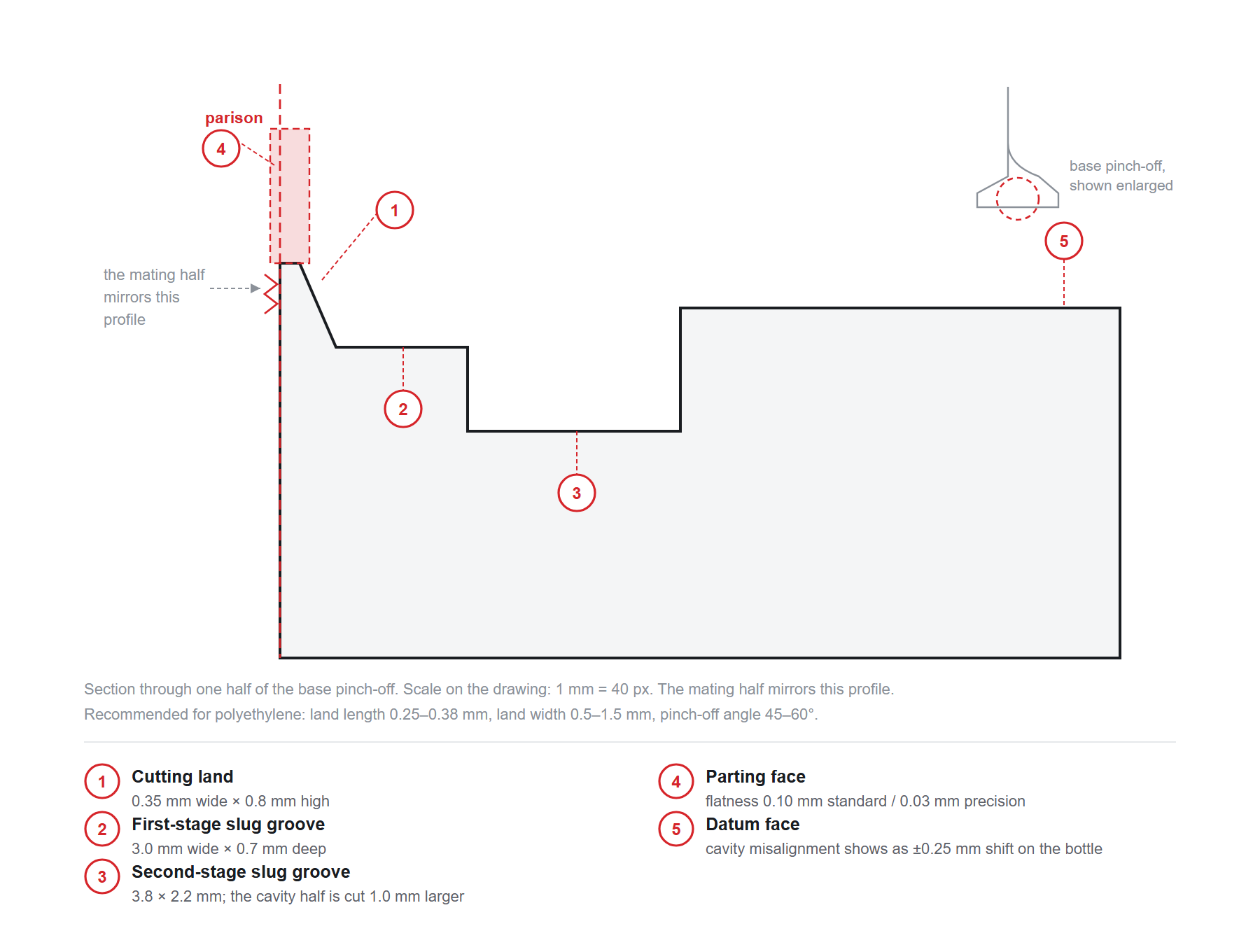
The cavity half is normally cut about 1.0 mm larger than the base on the second stage (4.8 mm × 3.2 mm) so the two halves do not fight each other along the weld.
3. Neck and preform locating insert
In EBM the neck is formed in the mold, which means the insert holding it sets the thread and the sealing surface — the two features a cap actually has to work with. A common specification is a cutting blade 0.4 mm wide × 1.6 mm high with a 1.9 mm first-stage groove; a neck datum of 2.2 mm × Ø29.0 mm suits a 30/25-style finish.
One detail explains how the insert is retained: the insert is 11 mm tall, but the pocket it sits in is cut to 10.9 mm. The insert is not screwed down — the upper neck plate clamps it with 0.1 mm of interference. That is why neck inserts are quoted as a replaceable item: a worn thread is swapped in minutes instead of re-cutting the cavity block. Inserts may be one-piece, or split into insert plus frame, depending on the neck geometry.
4. Backing plate
The backing plate is the machine interface, and its bolt pattern is not a design choice — it is fixed by the press. Centres of 420 mm, 75 mm and 125 mm are typical of a small-bottle EBM platen and cannot be altered. Dowels on one edge locate the trim unit; dowels on the other locate the cavity block. Every remaining hole is a clearance hole with a counterbore.
5. Automatic flash trim unit
The trim unit comprises upper and lower shear plates, a driving cylinder, and the fixed top plate and support plate. It matters commercially because the material it cuts is not scrap: in small-bottle work the neck flash and tail routinely amount to 30–40% of the parison weight, which is why a working trim unit feeds a closed regrind loop rather than a waste bin.
One drawing discipline carries a real risk of error: the trim unit is laid out around a cooled part, so the shrinkage factor has to be applied a second time to the shear geometry. Toolrooms that forget this deliver a trim unit that fits the drawing and not the bottle.
Steel grades and insert materials: what to specify and why
Material choice in a blow mold is a trade between cooling speed and wear life, and the decision is normally made per zone rather than for the whole block.
| Material | Thermal conductivity | Hardness | Where it belongs | Expected life |
|---|---|---|---|---|
| Aluminium 7075-T6 | 130–160 W/m·K | ~HB 150–175 | Cavity body, main block | 100k–500k cycles |
| Aluminium 6061-T6 | ~167 W/m·K | ~HB 95 | Medium-volume bodies, prototypes | Lower |
| Beryllium copper C17200 | 105–130 W/m·K | HRC 36–42 (aged) | Pinch-off and neck inserts | Replaceable insert |
| P20 (1.2311) | 29–36 W/m·K | HRC 28–35 | Base plates, long-run cavities | 1M+ cycles |
| H13 (1.2344) | ~30 W/m·K | HRC 42–52 after heat treatment | Pinch-off edges, neck rings | High |
| 718H (1.2738) | ~30 W/m·K | HRC 30–38 | Cosmetic and clarity surfaces, finer polish | 1M+ cycles |
| 4140 | — | HRC 28–36 | Structural components, backing plates | 1M+ cycles |
| Stainless 420 / 630 | ~25–30 W/m·K | HRC 38–50 | PVC, corrosive resins, medical | High |
| S136 (1.2083 ESR) | Low (stainless) | HRC 48–52 after heat treatment | PET preform core, cavity, neck screw | 3–5M shots |
| 2316 | Low (stainless) | HRC 48–52 after heat treatment | Alternative preform core and cavity | 3–5M shots |
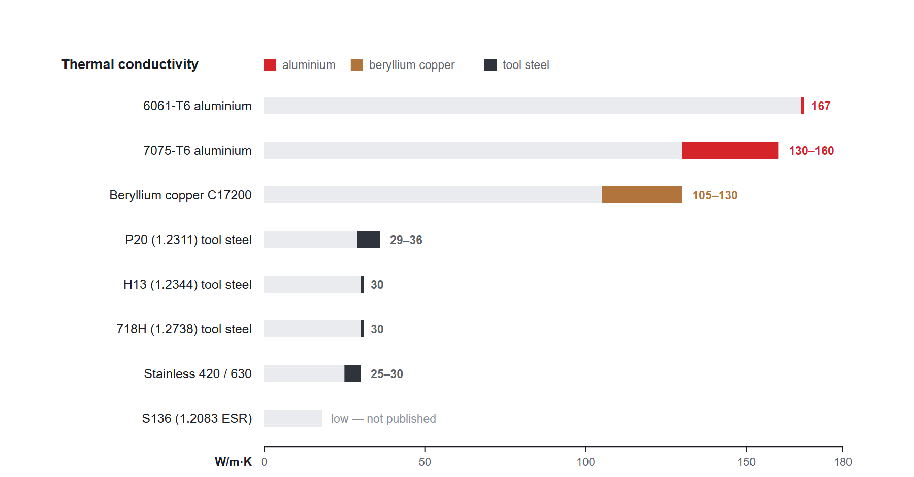
The industry-standard answer is a hybrid tool: an aluminium body for bulk cooling, with beryllium copper or hardened steel inserts at the neck and pinch-off, where the mold sees repeated clamping shear. It is also the cheapest arrangement over the life of the tool, because a worn insert is replaced rather than the whole block — and because switching between neck standards means swapping one insert, not buying a new mold.
Two practical exceptions. PVC and other resins that decompose into acidic products need stainless (420/630) despite the slower cooling, compensated with larger channels and colder water. And PET preform tooling is a different family entirely: core, cavity and neck screw are made from S136 stainless at HRC 48–52 after heat treatment, on a chrome-plated P20 base at HRC 30–35. That two-stage route is what makes the preform’s neck dimensionally stable enough to cap reliably — injection stretch blow molding explains where the preform and the blow mold split the work.
Cavity count: size the tool to the machine, not to the wish list
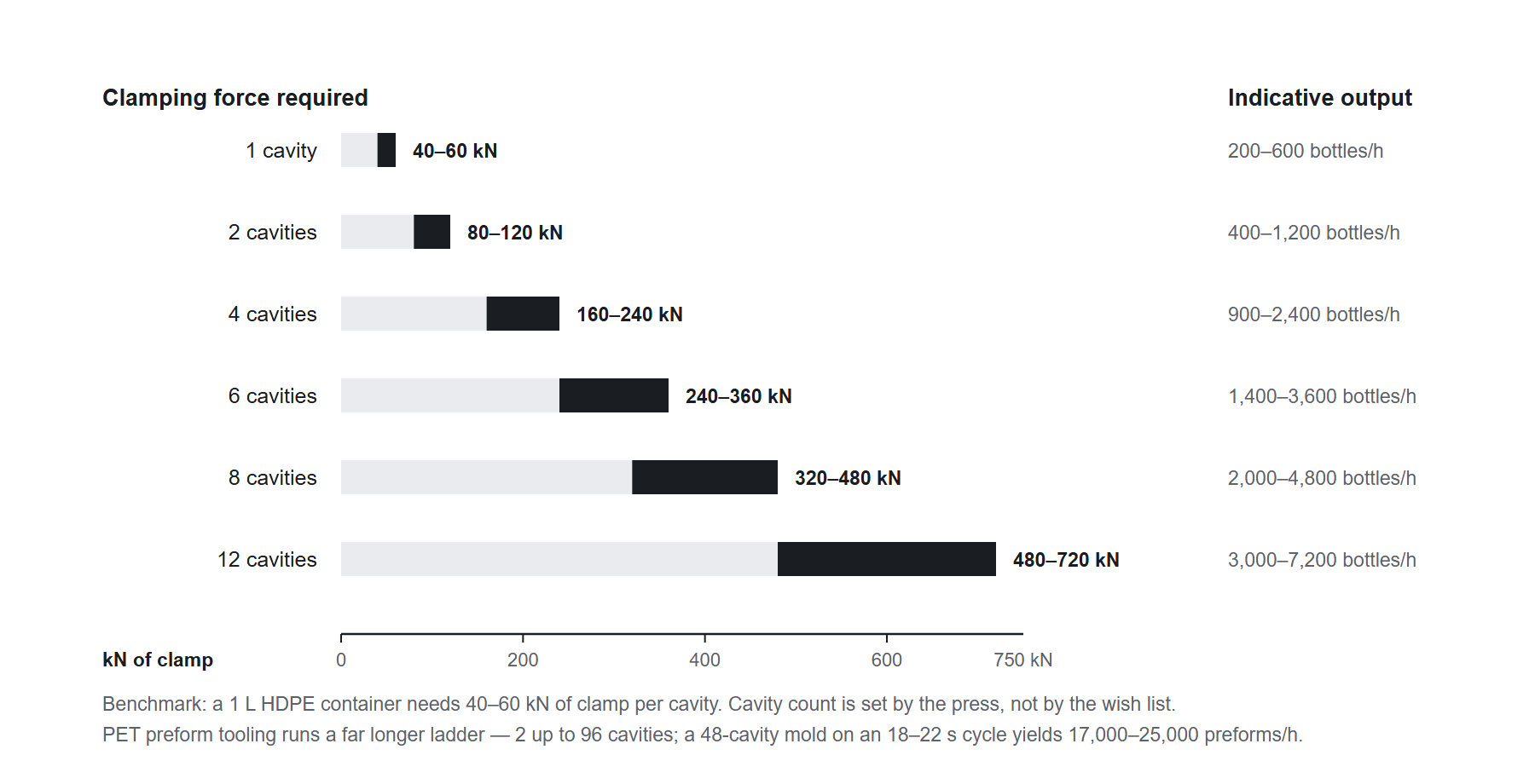
Cavity count is limited first by clamping force, not by the toolmaker. Blow pressure acts on the projected area of every cavity at once, so the required lock force scales roughly in proportion to cavity count — as a working benchmark, a 1 L HDPE container needs 40–60 kN of clamp per cavity.
| Cavities | Typical container size | Clamping force band | Die-head outlets | Indicative output |
|---|---|---|---|---|
| 1 | 5–1,500 L | Low | 1 | 200–600 bottles/h |
| 2 | 500 ml – 20 L | Low to medium | 1–2 | 400–1,200 bottles/h |
| 4 | 200 ml – 10 L | Medium | 2–4 | 900–2,400 bottles/h |
| 6 | 200 ml – 5 L | Medium to high | 3–6 | 1,400–3,600 bottles/h |
| 8 | 100 ml – 2 L | High | 4–8 | 2,000–4,800 bottles/h |
| 12 | 50 ml – 1 L | Very high | 6–12 | 3,000–7,200 bottles/h |
The second constraint is the die head. A head with two outlets cannot fill a six-cavity mold — the parisons either starve or land off-centre. Pitch, the centre-to-centre distance between adjacent outlets, must match the cavity centre distance within 0.1–0.2 mm. There is a subtlety here that catches even experienced toolmakers: the head runs at melt temperature while the mold runs cold, so the two pitches are not equal at operating temperature. The cold mold pitch is therefore cut slightly tighter than the nominal hot head pitch.
The third constraint is cooling. Adding cavities only raises output if the cooling circuit can still freeze every parison in the same window, which is why cavity count and cycle time have to be quoted together rather than separately.
For PET preform tooling the ladder runs much higher — 2, 4, 6, 8, 12, 16, 18, 24, 32, 36, 48, 56, 72 and up to 96 cavities, usually in balanced layouts such as 4×8 or 4×12. A 48-cavity preform mold running an 18–22 s cycle produces roughly 17,000–25,000 preforms per hour.
Tolerances: what the mold is held to, and what the bottle can achieve
These are two different sets of numbers, and quotations frequently conflate them.
| Mold feature | Standard tolerance | Critical tolerance |
|---|---|---|
| Overall mold dimension | ±0.15 mm | ±0.05 mm |
| Parting-line flatness | 0.10 mm | 0.03 mm |
| Core / cavity radius | ±0.08 mm | ±0.02 mm |
| Vent depth and width | ±0.05 mm | ±0.01 mm |
| Ejector pin location | ±0.05 mm | ±0.015 mm |
| Surface roughness (Ra) | 1.6 µm | 0.8 µm |
For sealing and alignment features, precision toolrooms hold tighter still: core and cavity surfaces ±0.005 mm, parison gap width ±0.003 mm, neck ring dimensions ±0.005 mm with 0.010 mm concentricity, parting-line fit ±0.008 mm with 0.012 mm flatness, and cooling channel bore ±0.010 mm.
What the bottle achieves is looser, because it is governed by the process rather than the tool:
| Molded feature | Typical tolerance |
|---|---|
| Wall thickness | ±10–20% of nominal |
| Height | ±0.5–1.0 mm |
| Diameter (neck, body) | ±0.3–0.8 mm |
| Sealing surface flatness | ±0.2–0.5 mm |
| Parting-line shift | ±0.25 mm |
| Preform weight variation, multi-cavity | <0.3 g across all cavities |
| Preform wall thickness variation | <0.10 mm |
| Preform concentricity | ±0.075 mm |
On the pinch-off specifically, the published recommendation for polyethylene is a land length of 0.25–0.38 mm (0.010–0.015 in), a land width of roughly 0.5–1.5 mm, and a pinch-off angle of 45–60°. Too short or too sharp and the weld thins and pulls into the bottle; too long and the halves cannot close fully, leaving a heavy flash line that tears.
Cooling: where cycle time is actually won
Cooling accounts for 60–80% of a blow molding cycle, which makes it the only lever with real leverage. Three rules govern it.
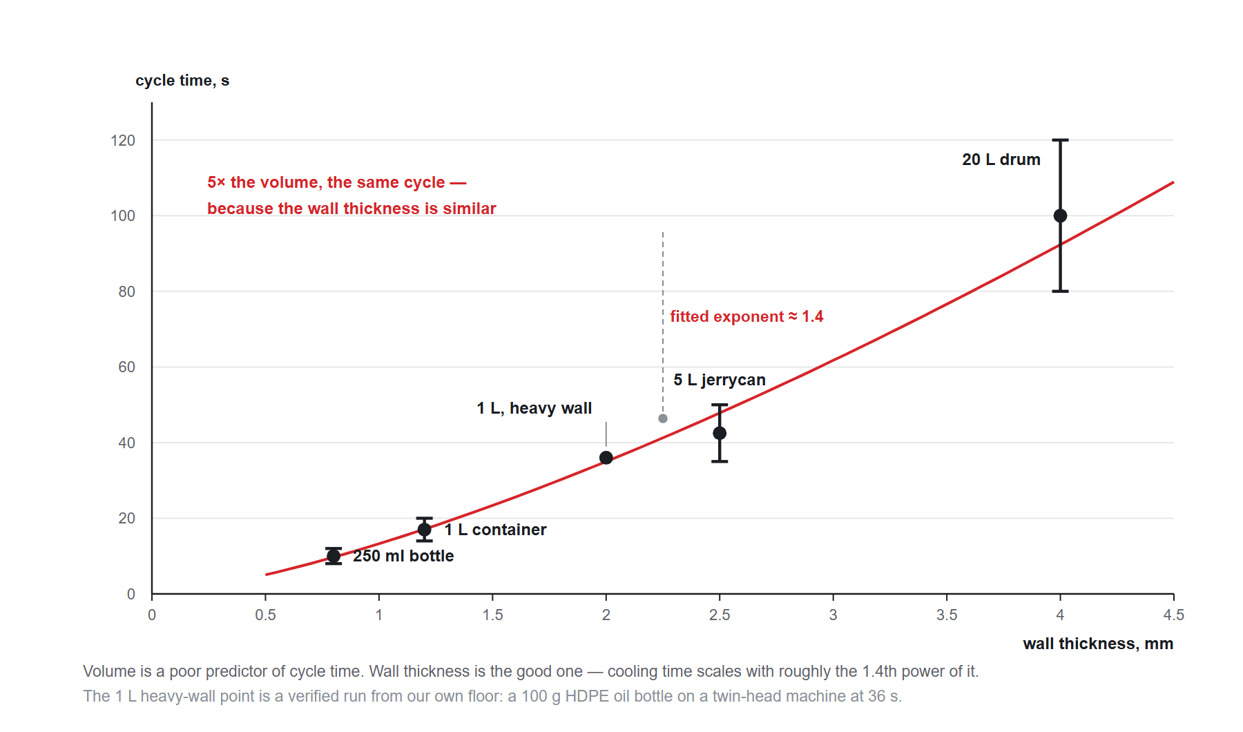
- Cooling time scales with the square of wall thickness. Doubling wall thickness roughly quadruples cooling time. This is why a 1 L bottle can run at 7–12 s in thin-wall and 14–20 s at a heavier wall — volume is a poor predictor of cycle time, wall thickness is the good one. (How wall thickness and material distribution affect bottle quality covers the measurement side of the same problem.)
- Flow must be turbulent. Straight-drilled channels running laminar transfer heat poorly. Turbulent flow alone is worth 15–25% of cycle time, and a properly engineered cooling layout is worth 20–40%.
- Channels belong close to the surface. A cooling channel is normally drilled within 10–15 mm of the cavity surface, and the base gets its own loop because it is the last zone to freeze.
The process window is narrow: melt 180–220 °C, mold water 10–40 °C, blow pressure 4–7 bar for general EBM, rising to 6–10 bar on high-output dairy lines.
Cycle time: real numbers by container size
| Container | Wall thickness | Cooling time | Total cycle |
|---|---|---|---|
| 250 ml bottle | 0.8 mm | 4–6 s | 8–12 s |
| 1 L container | 1.2 mm | 8–12 s | 14–20 s |
| 5 L jerrycan | 2.5 mm | 25–35 s | 35–50 s |
| 20 L drum | 4.0 mm | 60–90 s | 80–120 s |
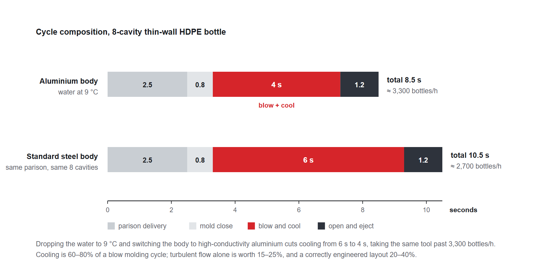
A worked breakdown for a thin-wall HDPE bottle on an eight-cavity tool: 2.5 s parison delivery, 0.8 s mold close, 6 s blow and cool, 1.2 s open and eject — 10.5 s per cycle, about 343 cycles per hour, roughly 2,700 bottles per hour. Switch the body to high-conductivity aluminium and drop the water to 9 °C, and cooling falls to 4 s, the cycle to 8.5 s, and the same tool passes 3,300 bottles per hour.
For a heavier container the numbers move sharply. A verified case from our own floor — a 1 L, 100 g HDPE oil bottle on a twin-head, twin-station machine — runs a 36 s cycle and about 340 bottles per hour. The difference between that and the thin-wall example is not the volume; it is roughly 2 mm of wall.
Shrinkage allowance: the number that quietly breaks neck fit
Shrinkage factors are applied to the product model before any mold geometry is cut, and the value is not a single number:
| Case | Factor applied |
|---|---|
| General small container | 1.005 |
| Large part, thick wall | 1.020–1.022 |
| Small part, thin wall | 1.016–1.018 |
| Transverse direction | 1.018 |
| Longitudinal direction | 1.016 |
Two consequences follow. First, directional factors exist because flow-oriented polyethylene shrinks differently along and across the flow direction — applying one isotropic factor moves the neck thread. Second, wherever the part is modelled after cooling — trim tooling, gauges, fixtures — the factor must be applied again to that geometry. Resin-supplier shrinkage tables always govern over general values.
Lead time: how long a mold really takes
For PET preform tooling, a standard multi-cavity mold runs 35–45 days from drawing approval to first samples; heavily customised tools with special neck finishes or stack layouts run 60–70 days. Blow molds for HDPE and PP containers typically sit at the shorter end, but the phase structure is identical: design and flow simulation, steel and standard-component procurement, rough machining, heat treatment, finish machining, polish and texture, trial (T0), correction, and approval samples (T1).
A recent reference from our own production: a 6-cavity PP essential-oil-bottle tool in heat-treated S136 ran 45 days from approved drawing to T1 samples. Heat treatment is the step that most often moves the date, because it is outsourced and cannot be compressed by adding machinists.
What to send a toolmaker for a binding quotation
- Bottle drawing with capacity, weight and target wall thickness
- Resin grade, including virgin or recycled (PCR) content, and colour
- Neck finish standard — PCO 1810, PCO 1881, 28 mm, 30/25, 38 mm — or a thread drawing
- Annual and peak volume, and the machine the tool will run on
- Decoration method (label, sleeve, screen print), because it drives surface finish and hand
- Cooling water available, in temperature and flow, and whether a chiller is in scope
- Required tool life, and whether the tool must be multi-cavity from the start
A quotation that does not state the cavity count, the steel grade at the pinch-off and neck, the cooling layout and the pinch-off land dimension is not a comparable quotation. Those four items are the difference between two tools that look identical on a specification sheet.
Building a tool for a bottle you have not made yet
We build extrusion blow, injection blow and injection stretch blow tooling for HDPE, PP and PET containers — from a single-cavity sample tool to 48-cavity preform molds — and we quote the cavity count, steel grades, cooling layout and pinch-off dimensions as part of the offer, not after the fact. Start from our HDPE bottle range, PET bottles, PP bottles, or the PET jar and PP jar ranges. For the surrounding decisions, read our guides to custom bottle mold design, blow molding vs injection molding, GCMI, SPI and PCO neck finish standards, choosing between PET, HDPE and PP, and MOQ, lead times and pricing.
 WeChat ID